You're reading the documentation for a development version. For the latest released version, please have a look at v0.2.
Additional (laser) background correction
Classes used:
Description
tr-EPR spectra are typically recorded as full time profiles for a series of magnetic field positions, and to obtain the full kinetics, it is crucial to record the time traces starting before the laser flash.
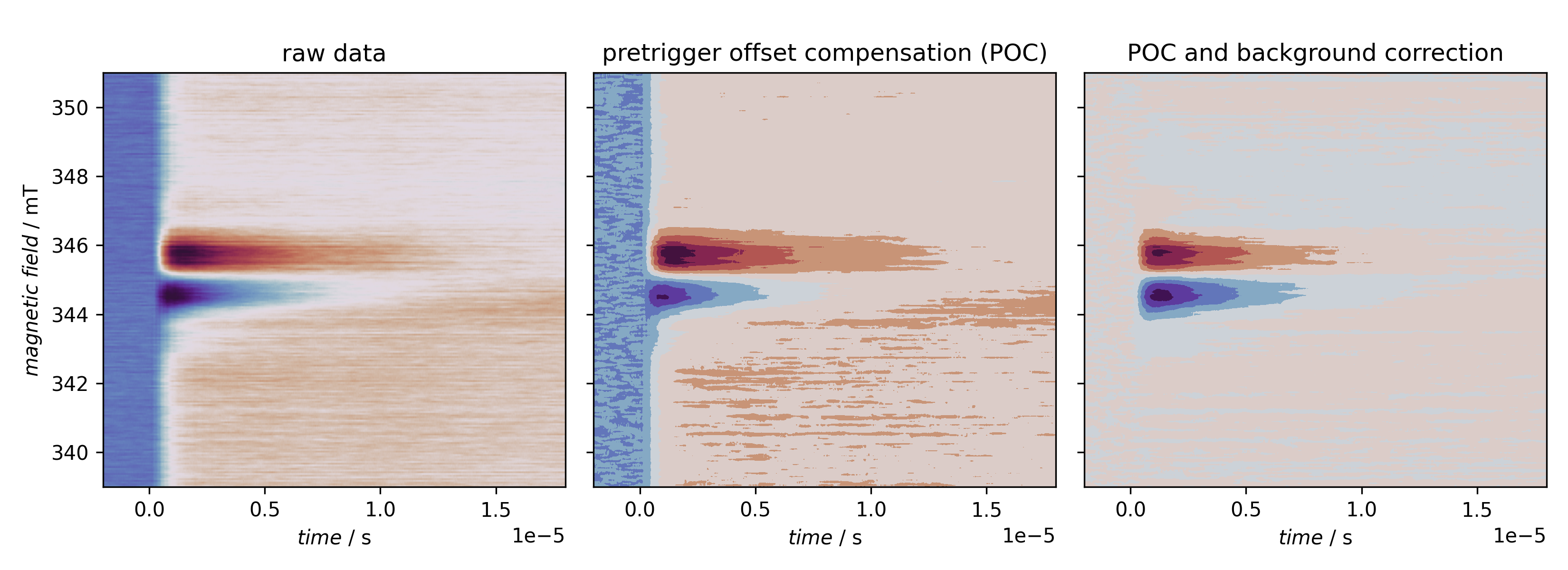
The part before the laser flash that triggers the actual measurement is usually termed “pretrigger offset”. The first preprocessing step of raw data is hence to take this pretrigger offset and set its average to zero, i.e. average over this part of the time trace and subtract this average value from the entire time trace. This removes any DC offset of the recording.
Additionally, the laser hitting the EPR cavity usually leads to a slight detuning that manifests itself in an (absorptive) background signal. Depending on the recording scheme used, this background is either subtracted already in the transient recorder or needs to be removed afterwards to be able to properly analyse the data.
A necessary prerequisite for performing such background correction afterwards is to record your data with sufficient range of the magnetic field on both sides of the actual signal that can be considered off-resonant, i.e. background, and hence used for background correction.
You can control the number of time traces used for the background correction on both ends of the magnetic field range. The crucial part of the recipe is shown below:
69  - kind: processing
70    type: BackgroundCorrection
71    properties:
72      parameters:
73        num_profiles: [10, 10]
Here, ten time profiles at both ends of the magnetic field range are used for calculating and subtracting the background. If you use time profiles at both ends of the magnetic field range, those profiles are averaged over and a linear interpolation performed between both ends. This allows to compensate for linear drifts in the background intensity.
The remainder of the recipe besides loading the data serves rather didactic purposes, such as plotting the raw and processed data and comparing extracted spectra before and after processing.
Recipe
  1format:
  2  type: ASpecD recipe
  3  version: '0.2'
  4
  5settings:
  6  default_package: trepr
  7  autosave_plots: false
  8
  9directories:
 10  datasets_source: ../../tests/testdata/fsc2/
 11
 12datasets:
 13  - radical-pair
 14
 15tasks:
 16  - kind: singleplot
 17    type: SinglePlotter2D
 18    properties:
 19      parameters:
 20        switch_axes: true
 21        tight_layout: true
 22      properties:
 23        figure:
 24          dpi: 300
 25        axes:
 26          title: "raw data"
 27        drawing:
 28          cmap: twilight_shifted
 29    result: plot-raw
 30  - kind: aspecd.processing
 31    type: Averaging
 32    properties:
 33      parameters:
 34        range: [0.8e-6, 1.0e-6]
 35        unit: axis
 36        axis: 1
 37    result: spectrum-raw
 38  - kind: processing
 39    type: PretriggerOffsetCompensation
 40    result: poc
 41    comment: >
 42        Compensate for DC offsets of the signal prior to the laser flash
 43  - kind: aspecd.processing
 44    type: Averaging
 45    properties:
 46      parameters:
 47        range: [0.8e-6, 1.0e-6]
 48        unit: axis
 49        axis: 1
 50    result: spectrum-poc
 51    apply_to:
 52    - poc
 53  - kind: singleplot
 54    type: SinglePlotter2D
 55    properties:
 56      parameters:
 57        switch_axes: true
 58        tight_layout: true
 59      properties:
 60        figure:
 61          dpi: 300
 62        axes:
 63          title: "pretrigger offset compensation (POC)"
 64        drawing:
 65          cmap: twilight_shifted
 66      type: contourf
 67    apply_to: poc
 68    result: plot-poc
 69  - kind: processing
 70    type: BackgroundCorrection
 71    properties:
 72      parameters:
 73        num_profiles: [10, 10]
 74    result: bgc
 75    apply_to: poc
 76    comment: >
 77        Correct for laser-induced background signal.
 78  - kind: aspecd.processing
 79    type: Averaging
 80    properties:
 81      parameters:
 82        range: [0.8e-6, 1.0e-6]
 83        unit: axis
 84        axis: 1
 85    result: spectrum-bgc
 86    apply_to:
 87    - bgc
 88  - kind: singleplot
 89    type: SinglePlotter2D
 90    properties:
 91      parameters:
 92        switch_axes: true
 93        tight_layout: true
 94      properties:
 95        figure:
 96          dpi: 300
 97        axes:
 98          title: "POC and background correction"
 99        drawing:
100          cmap: twilight_shifted
101      type: contourf
102    apply_to: bgc
103    result: plot-poc-bgc
104  - kind: compositeplot
105    type: CompositePlotter
106    properties:
107      properties:
108        figure:
109          dpi: 300
110          size: [11, 4]
111      grid_dimensions: [1, 3]
112      subplot_locations:
113        - [0, 0, 1, 1]
114        - [0, 1, 1, 1]
115        - [0, 2, 1, 1]
116      sharey: true
117      plotter:
118        - plot-raw
119        - plot-poc
120        - plot-poc-bgc
121      filename: basic-processing-overview.png
122      caption:
123        title: Overview of standard processing steps of tr-EPR data.
124        text: >
125            The first step is always to correct for DC offsets of the transients prior to the laser flash (POC), followed by subtracting the laser-induced background (BGC). The latter is sometimes carried out during data acquisition by regularly recording off-resonant transients and subtracting their signal within the transient recorder.
126  - kind: multiplot
127    type: MultiPlotter1D
128    properties:
129      parameters:
130        tight_layout: true
131        show_legend: true
132      properties:
133        figure:
134          dpi: 300
135        drawings:
136          - label: raw
137          - label: poc
138          - label: bgc
139      filename: basic-processing-spectra-comparison.png
140      caption:
141        title: >
142            Standard processing steps of tr-EPR data from the view-point of spectra taken near the signal maximum.
143        text: >
144            In this case, the pretrigger offset compensation (POC) does not have such a clear impact on the spectral shape, but clearly on position on the y axis. The background correction works similar to a polynomial baseline correction and operates on the complete two-dimensional dataset.
145    apply_to:
146      - spectrum-raw
147      - spectrum-poc
148      - spectrum-bgc
Result
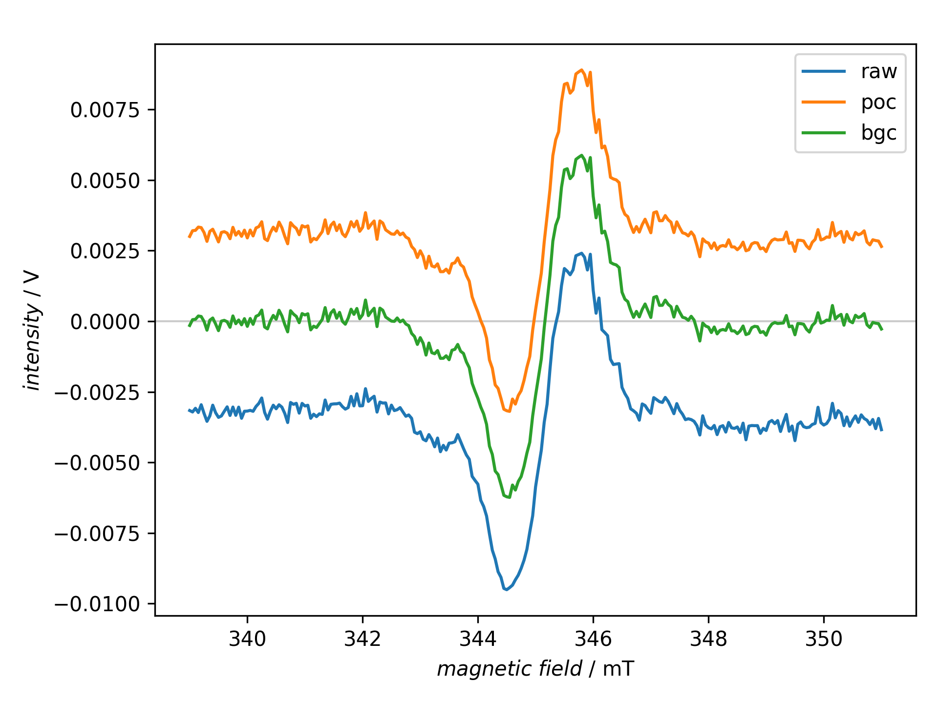
The recipe actually creates two figures presented afterwards.

Overview of standard processing steps of tr-EPR data. The first step is always to correct for DC offsets of the transients prior to the laser flash (POC), followed by subtracting the laser-induced background (BGC). The latter is sometimes carried out during data acquisition by regularly recording off-resonant transients and subtracting their signal within the transient recorder.

Standard processing steps of tr-EPR data from the view-point of spectra taken near the signal maximum. In this case, the pretrigger offset compensation (POC) does not have such a clear impact on the spectral shape, but clearly on position on the y axis. The background correction works similar to a polynomial baseline correction and operates on the complete two-dimensional dataset.